


Hello all of you. Today plc247.com will continue the series of instructions for controlling INVT-Goodrive 20 inverters using Modbus-RTU RS485 communication method.
And the PLC I choose today is the Omron CP1H PLC + CP1W CIF12 Module (or CP1W CIF11 is fine)
PLC Omron & INVT GD20 “Wiring Diagram”
If communicating with many slaves, or the communication distance is long, we need to add a 120Ω terminal resistor

INVT Goodrive 20 Modbus-RTU Configuration
In addition to the basic parameters of the inverter installed according to the motor, we need to configure additional communication parameters as follows:
- P00.01 = 2 (Motor Control via RS485 Port)
- P00.06 = 8 (Frequency Control via RS485 Port)
- P00.09 = 0
- P14.00 = 1 (Address No.1)
- P14.01 = 3 (9600bps)
- P14.02 = 1 (ModbusRTU 8/E/1)
- P14.03 = 5
- P14.04 = 0
Register for Control Motor
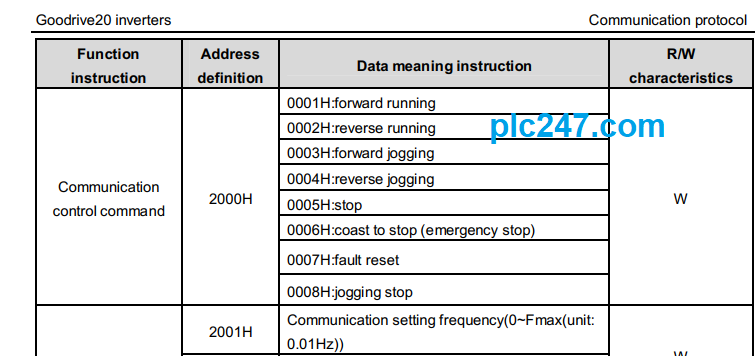
>>> Control Motor Address = 2000 (hex)
- Set 2000(Hex) = 1 >>> Run Forward
- Set 2000(Hex) = 2 >>> Run Reverse
- Set 2000(Hex) = 5 >>> Stop
>>> Setting Frequency Address = 2001 (hex)
Register for Data Monitoring

>>> Output Frequency = 3000 (hex)
>>> Output Voltage = 3003 (hex)
>>> Output Current = 3004 (hex)
CP1H Communication Setting
We need to configure the communication parameters of the PLC to be the same as the INVT GD20

PLC Omron Programming
+ Reset Data when PLC Start

+ Transmission Distribution

+ Frequency Write Command

+ Motor Control Run Command

+ Read Data Response

+ Data Monitoring

Detailed Instruction Video
======
Documention Requirements
INVT Goodrive 20 Manual PDF (Password: plc247.com)
Please comment and share the article to the community if you find it useful.
Thanks and best regards!
