1. What is RS-232?
RS232 is a communication standard developed by “Electronic Industry Association” and “Telecommunications Industry Association” abbreviated as EIA/TIA. This is a communication standard that was once very popular with the official name EIA/TIA-232-E, however it is often referred to as RS232 or RS-232. This standard only deals with serial data transmission between a host (DTE-Data Terminal Equipment) and a peripheral (DCE-Data Circuit-Terminating Equipment).
2. History of RS-232
The first version of RS232 was released in 1962 and logic levels were defined differently than TTL logic. At the output of a control circuit, the high level (corresponding to logic 0) is a voltage of +5 to +15 V, and the low level (corresponding to logic 1) is a voltage of -5 to -15 V. At the input of a receiver, the high level is defined as between +3 and +15 V (called space), and the low level is defined as between -3 and -15 V (called mark).
This communication standard has 2 versions used for a long time, which are RS232B and RS232C. However, now we only see the RS232C version and often referred to by the short name RS232. In computer hardware, there are usually 1 or 2 RS232C ports and are called COM ports. This COM port is usually divided into 2 types, 9 pins or 25 pins depending on the model, or the main computer (9-pin type is more common). Today, COM ports no longer appear on computers due to the appearance of more modern communication and connection ports.
3. Characteristics of RS232
- High anti-interference ability of serial ports
- Peripherals can be removed even when the computer is running
- Supply power supply voltage through the serial port
- Logic level 1 has a voltage ranging from -3V to -12V, logic level 0 from +-3V to 12V.
- The inputs must have a capacitance less than 2500pF.
- Load impedance must be greater than 3000 but must be less than 7000
- The length of the cable connecting two devices using the RS232 standard does not exceed 15m.
- Commonly used standard data rate values: 9600, 19200, 38400…. to 115200 bps
4. RS232 “Pin Function”
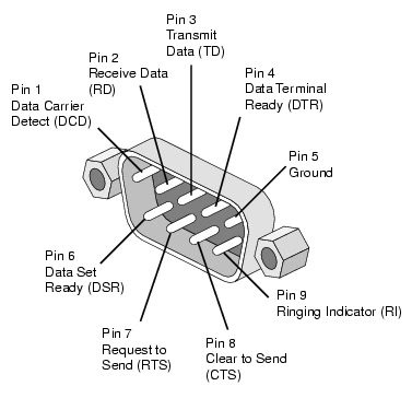
As mentioned above, RS232 has two main pins: 9 pins (DB9) and 25 pins (DB25). However, the DB25 type does not appear anymore, so we will focus and explore the DB9 type. RS-232 signals are defined at the DTE, according to the following table (only 9-pin connector signals are mentioned):
- Pin 1: Data Carrier Detect (DCD) : Transmit data carrier signal
- Pin 2: Receive Data (RxD) : Receive data
- Pin 3: Transmit Data (TxD): Transmit data
- Pin 4: Data Termial Ready (DTR) : The data terminal is ready to be activated by the component when it wants to transmit data.
- Pin 5: Singal Ground (SG) : Mass of signal
- Pin 6: Data Set Ready (DSR) : Data ready, activated by the transmitter when it is ready to receive data
- Pin 7: Request to Send : request to send, transmitter sets this line to active when ready to transmit data
- Pin 8: Clear To Send (CTS): Clear to send, the receiver sets this line to active level to notify the transmitter that it is ready to receive the signal
- Pin 9: Ring Indicate (RI) : Ringing indicates that the receiver is receiving a ring signal
5. Data transmission according to “RS232 Standard”
Data transmission over the RS232 serial port is performed asynchronously. Therefore, only one bit can be transmitted at a time (1 character). The transmitter sends a start bit to notify the receiver of a character to be sent in the next bit transmission. This bit always starts with zero. This is followed by data bits (bits) that are sent as ASCII codes (which can be 5,6,7 or 8 data bits). Then an even and odd check bit (Parity bit) and finally a stop bit (stop bit) which can be 1, 1.5 or 2 stop bits.
6. “Baudrate” data transfer rate
This is a characteristic parameter of RS232. This parameter is specific to the data transmission process over the RS232 serial port, which is the data transmission rate, also known as the bit rate. Bit rate is defined as the number of bits transmitted per unit of time (seconds). This bit rate must be set to the same on both the transmitter and the receiver.
Some commonly used baud rates: 4800, 9600, 19200, 28800, 38400, 56000, 115200 … In commonly used devices, the rate is 19200 bps
When using the RS232 serial standard, the standard usage requirement is that the logic level transition time does not exceed 4% of the 1-bit transmission time. Therefore, the higher the bit rate, the smaller the 1-bit transmission time, the smaller the logic transition time. This limits the baud rate and transmission distance.
Parity bit
This is the error checking bit on the line. The essence of the error checking process when transmitting data is to add more data to be transmitted to find or correct some errors during transmission. Hence in the RS232 standard a parity check technique is used.
A parity bit is added to the transmitted data to indicate whether the number of “1” bits sent in a transmission frame is even or odd.
A parity bit can only find an odd number of errors such as 1,3,,5,7,9… If an even bit is erroneous, the parity bit will be the same value as the error-free case. no error detected. Therefore, this error coding technique is not used in cases where there is a possibility that some bits are in error.